Register now or log in to join your professional community.

Supposed you have a layer MyLines with color Red and linetype hidden, and set current layer to Mylines, linetype=continuous, color=Yellow Draw a line, line is in layer MyLines with color yellow and linetype continuous If you click on line, open panel property and change color=bylayer and linetype=bylayer you see line changed in color=red and linetype=hidden (because line is in Mylines with color=red and linetype=hidden). If you change definition layer MyLines from color Red to Blue, automatically line change proper color from Red to Blue (because line has color Bylayer)

Beautiful Answers are given by Mr. Yaqoob and Ms. Elke Woofter. I endorse their answers.
Regards.

I agree with Mr. Yacoup answer ..thank you

Each layer in an AutoCAD drawing has a default colour and a default linetype. Thus, the term "Bylayer" means that an object drawn on a particular layer has the default colour and linetype of that layer.

Every AutoCAD object, such as a line or a circle has properties. Some properties such as Colour, Linetype and Layer are common to all objects. Some objects have properties which are specific to themselves. Text, for example, is the only object type which has a Text Style property. In AutoCAD Release14, the easiest way to control object properties is to use the Object Properties toolbar, illustrated below. This is one of AutoCAD's default toolbars and can usually be found directly below the Standard toolbar in the top left hand corner of the AutoCAD window.
Take time to work through this tutorial, it is particularly important to get to grips with object properties since it can make the difference between a really good AutoCAD drawing and a really terrible one. If you just need information quickly, use the QuickFind toolbar below to go straight to the information you need or select a topic from the contents list above.
Layers
Probably the most important object property to understand well is the layer property. Experienced AutoCAD users use layers all the time and that is why the Object Properties toolbar contains so many layer functions. Good use of layers is the most important aspect of good drawing practice.
The concept of layers is very important in AutoCAD and the correct use of layers can make your drawing much easier to work with. Basically, layers are the computer equivalent of tracing overlays on a drawing board. However, layers are much more powerful because you can have many layers in a single drawing and you can control the visibility, colour and linetype of layers independently. This makes working with very complicated drawings much more efficient. Layers are effectively a way of ordering your drawing. For example, you may need to create a number of construction lines in a drawing which will not form a part of the finished image. You could create a layer called "Construction" and use this for your construction lines. When the drawing is complete, you could simply turn this layer off so that it can't be seen. The beauty is that you could always turn this layer back on at some future time if modifications to the drawing are required. Experienced AutoCAD users will use layers to order their drawings by drawing components. For example, if you were creating a landscape masterplan, you may have layers called "Trees", "Shrubs", "Path" etc. The main reason for this, apart from it being a simple way to control the drawing, is that the different drawing components may need to be printed in different colours, with different linetypes and with different line widths. Layers can be used to control the way objects are displayed on the computer monitor and how they appear when they are printed.
It is a common misapprehension amongst new users that layers can be used to control the visual hierarchy of objects. In other words, if two objects overlap, it seems reasonable to assume that you could cause one object to display "above" another with the use of layers. This layer model is common to illustration software such as CorelDRAW. However, AutoCAD uses a3 dimensional drawing space where all objects coexist and are positioned in their correct co-ordinate locations. The concept of an object being displayed above or below another, therefore, is not consistent with this logic. In AutoCAD the display of one object in relation to another is determined by the objects place in the drawing database. Objects drawn more recently will display over another if the two objects occupy the same physical space. It is possible to override this effect using the Display Order tools found on the Tools pull-down, Tools![]() Display Order
Display Order![]() Options. These options are particularly useful to control the display of overlapping solids and solid hatches that are coplanar. The layer of an object has no effect on its display order.
Options. These options are particularly useful to control the display of overlapping solids and solid hatches that are coplanar. The layer of an object has no effect on its display order.
Although you can have many layers in a drawing, you can only draw on one layer at a time. The layer you are drawing on is said to be the current layer. The Object Properties toolbar displays the current layer information. In the illustration above, you can see that layer "0" is the current layer and that both the colour and linetype are set "ByLayer".
When you start a new drawing, AutoCAD has only one layer. This layer is special and is called layer "0" (zero). Layer0 is special because you cannot change its name or delete it and it has certain properties which we do not need to consider just now. By default layer0 is assigned the colour white (colour number7) and the "Continuous" linetype. Layer0 is always the current layer when you start a new drawing, however, it is bad drawing practice to use layer0 for normal drawing. The first thing you should do, therefore, when you start a new AutoCAD drawing is to create some new layers.
The Layer Command
ToolbarAlthough AutoCAD provides many shortcuts for working with layers, many of which will be covered later, the Layer command provides the most comprehensive control over layers and layer operations. This command uses a dialogue box. The dialogue box is a tabbed dialogue box and can be modified to show more or less details. This is quite nice because in its simplified form it looks much less intimidating to beginners. The following setions demonstrate how the Layer command can be used to perform many of the most common layer operations.
Creating a New Layer
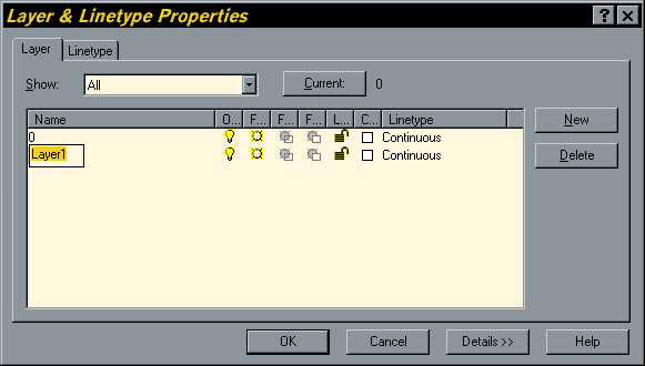
To create a new layer, click on ![]() in the Object Properties toolbar, the Layer & Linetype Properties dialogue box, illustrated below, appears. This is a tabbed dialogue box and can be used to control either layer properties or linetype properties depending upon which tab is selected. The Layer tab is always selected by default. Now click on the "New" button. A new layer called "Layer1" is automatically created in the layer list below layer0. As you can see from the illustration, the layer name is automatically highlighted for you so that you can give the layer a more meaningful name. When you have entered an appropriate name, press the
in the Object Properties toolbar, the Layer & Linetype Properties dialogue box, illustrated below, appears. This is a tabbed dialogue box and can be used to control either layer properties or linetype properties depending upon which tab is selected. The Layer tab is always selected by default. Now click on the "New" button. A new layer called "Layer1" is automatically created in the layer list below layer0. As you can see from the illustration, the layer name is automatically highlighted for you so that you can give the layer a more meaningful name. When you have entered an appropriate name, press the ![]() key to complete the operation. You have now created a new layer and given it a name. Notice that by default it has been assigned the colour white and the linetype "Continuous".
key to complete the operation. You have now created a new layer and given it a name. Notice that by default it has been assigned the colour white and the linetype "Continuous".
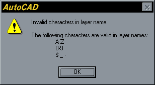 There are a few restrictions to consider when you are naming layers. The most annoying is that you cannot use spaces within layer names. So, for example, the layer name "Tree trunk" is illegal. However, it is common practice to replace the space with either a hyphen or an underscore, both of which are valid layer name characters. So, the layer names "Tree-trunk" and "Tree_trunk" are both acceptable. Some other special characters are also not allowed. If you do use an illegal character, AutoCAD will alert you with the error message box illustrated above. Notice that it very helpfully tells you which characters are legal. Basically, if you stick with letters and numbers you won't experience any problems. In addition to the hyphen and underscore mentioned above, the dollar sign is the only other symbol allowed.
 The only other restriction relating to layer names is the number of characters used. Layer names can be between one and thirty-one characters long. This should give you plenty of scope to devise understandable and descriptive names for your layers. It is good drawing practice to name your layers sensibly, bear in mind that other people may have to work with drawings which you create. If you enter a layer name longer that31 characters, AutoCAD will display the error message box shown on the left.
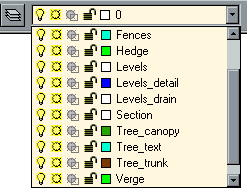 Layers are always listed alphabetically in layer lists, the user has no other way to control the list order. It is worth bearing this in mind when naming your layers. Keep similar object layers together by devising a hierarchical naming structure. For example, if you are drawing a tree symbol which comprises a number of elements, your layer names might be, "Tree_canopy", "Tree_text", "Tree_trunk" etc. This will cause all the Tree layers to be displayed together, see the illustration on the right. This is quite important because in complicated drawings there may be many layers and searching for the right group of layers can waste a lot of time.
Setting Colour and Linetype "ByLayer"
AutoCAD offers two methods of setting the colour and linetype of a drawing object. First of all, colour and linetype can be set ByLayer. In other words, an object will be displayed in the colour and linetype of its layer. For example, if you draw a circle on a layer which you have called "Detail" and you have also set the colour of Detail to blue and the linetype to dashed, then the circle will be displayed in a dashed blue line. When an object takes on the properties of its layer, the colour and linetype are said to be set "ByLayer".
The second method AutoCAD offers is to set the colour and linetype by object. Setting properties by object overrides those set ByLayer. In general it is good drawing practice to set colour and linetype properties ByLayer, this is more efficient and less confusing in the long-run. For example, imagine that you have drawn hundreds of objects on the same layer and have set their colour to green. Later in the drawing process you decide that these objects should, in fact, be yellow. In order to make the change you would have to use the Properties command and select every one of the objects by picking them. By contrast, if you had set the objects colour to ByLayer, you would only have to change the layer colour from green to yellow and all of the objects would change.
There are times , however, when in is useful to be able to set colour and linetype properties by object. Setting properties by object is covered later in this tutorial. The following sections cover the setting of colour and linetype ByLayer.
Setting the Colour of a Layer
It is often convenient to set the layer colour when the layer is created, although this can be done at any time. The layer colour can be changed as many times as you like. Each time it is changed, any objects on that layer will change to the new colour, providing their colour is set to "ByLayer".


To set a layer colour, open the Layer & Linetype Properties dialogue box, click on ![]() and then click on the colour icon in the layer list associated with the layer you want. Notice that all layers have their own colour icon and that this changes to display the layer colour. Clicking on the icon brings up the Select Color dialogue box, shown on the right. You can select any of the255 standard AutoCAD colours by picking on the colour palette or by entering the colour name or number in the text edit box. When you have selected the colour you want, click on the "OK" button to set the colour. AutoCAD uses only255 colours plus the drawing background colour, irrespective of the capabilities of your video display.
and then click on the colour icon in the layer list associated with the layer you want. Notice that all layers have their own colour icon and that this changes to display the layer colour. Clicking on the icon brings up the Select Color dialogue box, shown on the right. You can select any of the255 standard AutoCAD colours by picking on the colour palette or by entering the colour name or number in the text edit box. When you have selected the colour you want, click on the "OK" button to set the colour. AutoCAD uses only255 colours plus the drawing background colour, irrespective of the capabilities of your video display.
Assigning different colours to your layers will make working with complex drawings much easier. You will be able to see at a glance what a particular line represents. For example, your construction lines may be on a layer called "Construction" and have the colour yellow. This will visually differentiate these lines from lines on other layers with different colours.
Setting the Linetype of a Layer
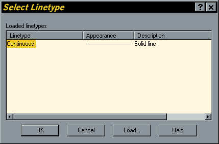
In the same way that you can assign a colour to a layer you can also assign a linetype to a layer. For example, you could have all the lines on a layer called "Construction" display in a yellow dashed line. To set a linetype to a layer, click on ![]() and then click on the current linetype name associated with your layer in the layer list. By default, layers have the "Continuous" linetype. Clicking on the linetype name brings up the Select Linetype dialogue box, shown on the right. You will notice that the "Continuous" linetype is the only one listed. That's because all linetypes, except "Continuous", are stored in an external file and have to be loaded before they can be used.
and then click on the current linetype name associated with your layer in the layer list. By default, layers have the "Continuous" linetype. Clicking on the linetype name brings up the Select Linetype dialogue box, shown on the right. You will notice that the "Continuous" linetype is the only one listed. That's because all linetypes, except "Continuous", are stored in an external file and have to be loaded before they can be used.
Loading Linetypes
To load a linetype, click on the "Load..." button in the Select Linetype dialogue box. The Load or Reload Linetypes dialogue box appears and displays a list of the available linetypes. Select as many of the listed linetypes as you wish and then click the OK button to return to the Select Linetype dialogue box.

Selecting from list boxes works the same way in AutoCAD as it does in any other Windows application. For example, if you wish to select a block of linetypes from the list at one time, select the first linetype in the block, hold the Shift key down on the keyboard and select the last linetype in the block. All linetypes in the block will be highlighted and you can click the "OK" button to load them all in one go. You can also hold the Control (Ctrl) key down on the keyboard to make multiple selections which aren't adjacent in the list (see illustration above).
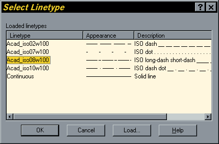
When you return to the Select Linetype dialogue box the loaded linetypes are displayed in the list. To assign a particular linetype to a layer, simply click on the name to highlight it and then click on the OK button. When you return to the Layer & Linetype Properties dialogue box, the new linetype name will be listed against your layer in the "Linetype" column. From now on, all objects drawn on this layer will be drawn with the chosen linetype. However, just like colours, you may change the linetype at any time and the objects drawn on that layer will automatically be updated to display the new linetype.
Making a Layer the Current Layer
Once you have created some layers you will want to start using them. As indicated above, you can only draw on one layer at a time. In order to draw on a particular layer you must first make it the current layer. As usual with AutoCAD there are a number of alternatives. You could, for example, use the Layer command, Layer... from the Format pull-down or ![]() from the Object Properties toolbar. As you have seen previously, this command brings up the Layer & Linetype Properties dialogue box. To set the current layer, select a layer name from the list and then click on the "Current" button and then click the "OK" button to finish. The selected layer is now the current layer and it's properties are displayed on the Object Properties toolbar.
from the Object Properties toolbar. As you have seen previously, this command brings up the Layer & Linetype Properties dialogue box. To set the current layer, select a layer name from the list and then click on the "Current" button and then click the "OK" button to finish. The selected layer is now the current layer and it's properties are displayed on the Object Properties toolbar.
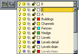 Most experienced AutoCAD users change the current layer so frequently that the above method starts to seem very long winded. It is much quicker and therefore more efficient to set the current layer directly from the Object Properties toolbar using the "Layer Control" drop-down list. To set the current layer, click on the down arrow next to the Layer Control window to reveal the layer list. Simply click on the name of the layer you wish to make current. If the layer name is not visible because the list is quite long, scroll down the list until you see it. The drop-down list only displays10 layers at a time. As a beginner, you may feel that this is quite a lot but a complex and well structured drawing may have50 or100 layers.
There is an even quicker way to change the current layer providing you know which layer objects are on. You can use the Make Object's Layer Current command to set the current layer to the layer of any picked object.
Select Make Object's Layer Current from the Object Properties toolbar. ![]()
When AutoCAD promptsSelect object whose layer will become current:pick the object you know to be on the required layer. If you miss the object you are trying to select, the command is automatically canceled
AutoCAD confirms the action by writing to the command lineLAYER NAME is now the current layer.You will also see the layer details change in the Object Properties toolbar. With a bit of practice and a good awareness of the layers you are using, this command can save lots of time.
Controlling Layer States
One of the best aspects of working with layers is the flexibility with which you can control their visibility. So far we have looked at the colour and linetype properties of layers. However, there are a number of other properties all of which relate to whether or not objects on a layer can be seen and/or modified. The current state of these properties are all indicated by icons in the various layer lists. You will already have seen them if you have been following this tutorial. The meaning of these icons is shown in the table below:
IconNameDescriptionTurning Layers On and Off
You can turn layers off or on either by using the Layer command, ![]() from the Object Properties toolbar or you can more easily do it using the "Layer Control" list, directly from the Object Properties toolbar. In either case, all you have to do is click on the icon you wish to change. The icons all act as toggles, so if a layer is on, all you need to do is click on the
from the Object Properties toolbar or you can more easily do it using the "Layer Control" list, directly from the Object Properties toolbar. In either case, all you have to do is click on the icon you wish to change. The icons all act as toggles, so if a layer is on, all you need to do is click on the ![]() icon and the icon will change to
icon and the icon will change to ![]() , turning the layer off. And conversely, clicking on
, turning the layer off. And conversely, clicking on ![]() changes the icon to
changes the icon to ![]() and turns the layer back on.
and turns the layer back on.
Objects on a layer which is turned off aren't displayed in the drawing window and they won't be plotted. The objects still exist in the drawing; they are just invisible.
If a layer is turned off and you make it the current layer, AutoCAD turns it on. It's possible to turn off the current layer, but this is rarely desirable. To do so causes no harm, but it can be confusing if you don't realise what has happened; new objects you draw are added to the drawing but are not displayed until the layer is again turned on.
Each designated layer is turned on (made visible) using the colour number and linetype previously associated with it. If the layer is presently frozen, turning it on is not sufficient to make it display again; you must also thaw the layer (see Freezing and Thawing Layers below).
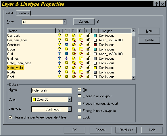
The illustration above shows the Layer & Linetype Properties dialogue box with a number of layers in different states of visibility. Notice also that the dialogue box has been enlarged to show more information. You can do this by clicking on the "Details>>" button.
Freezing and Thawing Layers
Freezing and thawing layers works in exactly the same way as turning them off or on. Simply click on the ![]() icon to freeze a layer or
icon to freeze a layer or ![]() to thaw it.
to thaw it.
By freezing a layer you are effectively instructing AutoCAD to ignore the objects on that layer when regenerating the drawing. Objects on frozen layers aren't displayed or plotted, and AutoCAD spends no time calculating where they go. Therefore, by freezing layers you can increase the ZOOM, PAN, VPOINT, REGEN, and object selection performance for complex drawings. It is always a good idea to freeze layers that aren't of immediate interest.
Turn Off or Freeze?
Since freezing a layer also makes it invisible, you may be confused about when to select Freeze as opposed to Off. The main difference is a matter of efficiency. If you're frequently switching between layers and changing their visibility, doing a bit of editing on each of them, you should use Off when you want to make objects on a layer invisible. If, on the other hand, you're doing most of your editing on one layer (or a set of layers), and don't need to see the objects on another set of layers, you should freeze those layers. This will speed up your editing and make the drawing clearer to work with.
Objects on layers that are off are recalculated during a regeneration, but simply not displayed. Therefore, when you turn a layer on that was previously off, it will display immediately. On the other hand, layers that are frozen are not recalculated during a regeneration and therefore REGENs and object selection can be much faster because there is less work for AutoCAD to do. When a frozen layer is thawed, however, a regeneration must be performed before objects on that layer can be displayed.
Locking and Unlocking Layers
Locking and unlocking layers work as for turning layers off and on and freezing and thawing them. Simply click on ![]() to toggle an unlocked layer so that it becomes locked and click
to toggle an unlocked layer so that it becomes locked and click ![]() to reverse the process.
to reverse the process.
You can't select or edit the objects on a locked layer; however, the objects are still visible if the layer is on and thawed. This is handy if you are working in detail, but don't want to inadvertently select certain objects. You can make a locked layer current, so you can draw on a locked layer. You can also use inquiry commands (such as LIST or ID) on locked layer objects. You can also use Object Snaps with objects on locked layers and you can even use them as Trim and Extend boundaries.
Layers in Viewports
AutoCAD beginners can operate quite effectively using the On/Off, Freeze/Thaw and Lock/Unlock layer states. However, when you start using Paper Space you will need to understand how to control the visibility of layers in different viewports. By default, all layers are visible in all viewports. However, you can use the "Freeze in current viewport" option to selectively freeze layers in different viewports. This is done by clicking the ![]() icon in a layer list when you are in Floating Model Space. This subject is covered in greater detail in the Paper Space tutorial. The viewport layer icons are greyed out when you are in Tiled Model Space.
icon in a layer list when you are in Floating Model Space. This subject is covered in greater detail in the Paper Space tutorial. The viewport layer icons are greyed out when you are in Tiled Model Space.
Renaming a Layer
To rename a layer, start the Layer command by clicking on the ![]() button on the Object Properties toolbar. When the Layer & Linetype Properties dialogue box appears, click on the "Details>>" button to reveal the layer details. Pick the layer name you wish to change from the layer list. The name appears in the Name text edit box under "Details". Simply edit or retype the name in the edit box and you will see the name change simultaneously in the layer list. You cannot rename layer "0", the deafault layer, nor can you rename a layer called "Defpoints" which AutoCAD creates automatically when you use Dimensions (see Dimensioning). In theory you can also edit a layer name directly from the layer list but I have always found this to be a bit tricky. Notice that you can also change the layer colour and linetype using the "Details" section of the dialogue box.
button on the Object Properties toolbar. When the Layer & Linetype Properties dialogue box appears, click on the "Details>>" button to reveal the layer details. Pick the layer name you wish to change from the layer list. The name appears in the Name text edit box under "Details". Simply edit or retype the name in the edit box and you will see the name change simultaneously in the layer list. You cannot rename layer "0", the deafault layer, nor can you rename a layer called "Defpoints" which AutoCAD creates automatically when you use Dimensions (see Dimensioning). In theory you can also edit a layer name directly from the layer list but I have always found this to be a bit tricky. Notice that you can also change the layer colour and linetype using the "Details" section of the dialogue box.
Deleting a Layer
To delete a layer, start the Layer command, ![]() from the Object Properties toolbar to open the Layer & Linetype Properties dialog box. Click the name of the layer to highlight it, click the "Delete" button and then click "OK".
from the Object Properties toolbar to open the Layer & Linetype Properties dialog box. Click the name of the layer to highlight it, click the "Delete" button and then click "OK".
You cannot delete any layer which has objects on it, you cannot, therefore, use this process to delete all of the objects on a particular layer. You cannot delete the current layer, layer "0", layer "Defpoints" or any layers from external references.
Purging Layers and Linetypes
Layer and linetype definitions add to the size of your drawing because they are kept in the drawing's database. It is, therefore, worthwhile purging layers and linetypes that you are not using. You can delete them (see Deleting a Layer), but it is often difficult to know which layers contain objects and therefore can't be deleted. The Purge command lets you delete many types of unused definitions, including blocks, dimension styles, layers and linetypes. You will find the Purge command on the pull-down menu at File![]() Drawing Utilities
Drawing Utilities![]() Purge
Purge![]() Options, there is no toolbar button for this command.
Options, there is no toolbar button for this command.
Command: PURGEPurge unused Blocks/Dimstyles/LAyers/LTypes/SHapes/STyles/Mlinestyles/All: (select option)Names to purge <*>: (type ![]() to delete all eligible definitions or specify particular names)Verify each name to be purged? <Y> (Type N to automatically purge all eligible definitions)
to delete all eligible definitions or specify particular names)Verify each name to be purged? <Y> (Type N to automatically purge all eligible definitions)
The Purge command may not always remove all of the definitions you expect. This usually occurs if you have block definitions in a drawing which reference layers or linetypes etc. In such a case the Purge command will remove any unused block definitions but will not remove the other dependent definitions. All you have to do to get rid of these definitions is to run the Purge command a second time after the block definition has been removed.

BYLAYER means an object will get its property from the value assigned for that property to the layer.

Yap agree with specialties.

When an Architect has to make a building drawing, the Architect may not want to show all portions of the building at once, say if he wants to concentrate on making construction drawings of one portion. The layer will then overlap if necessary on the other layer. For example, Layers of Electrical wires may overlap the cement wall etc.


Do you need help in adding the right keywords to your CV? Let our CV writing experts help you.